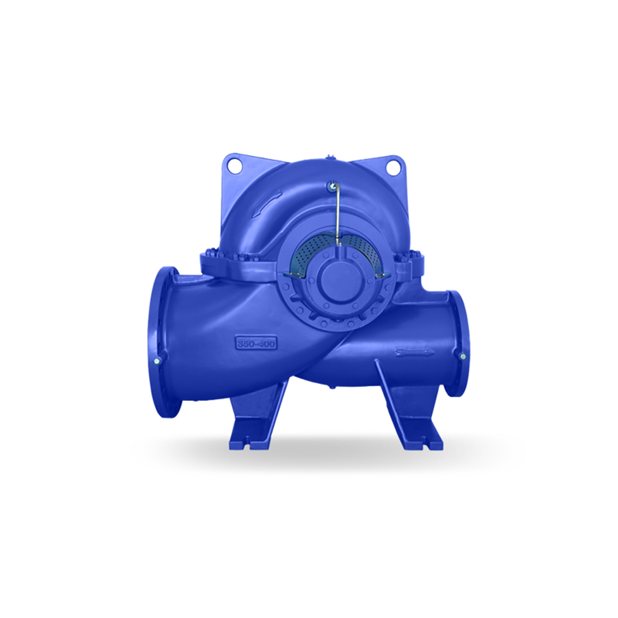
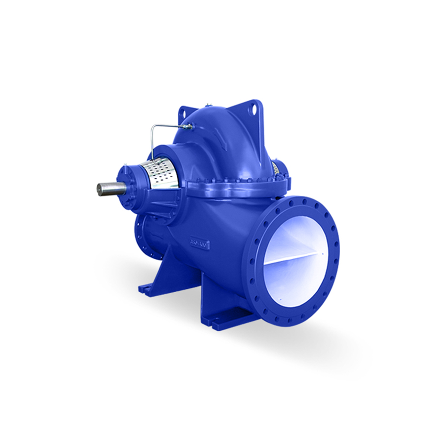
Suction and discharge flanges are on the same axis line. The double-suction design reduces axial forces by directing flow into both sides of the impeller. The double-volute design, available on most models, reduces the radial load and minimizes noise and vibration.
Suction and discharge flanges are PN 16 according to EN 1092-2 (DIN2501).
Seal box is cooled with water. Seals are easily dismountable, which makes replacing and fitting up additional seals easy.
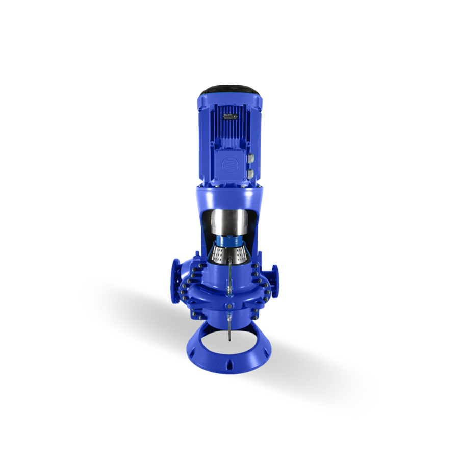
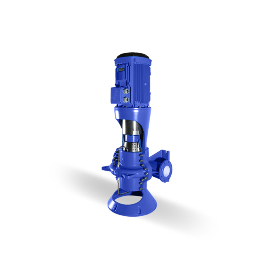
Split-case pumps could manufacturing horizontal or vertical.
The impellers are dynamically balanced according to ISO 1940 class 6.3.
Direction of rotation is clockwise when viewed from the motor in standard manufacture. In this case, the suction flange is on the right side. If required, the direction of rotation can be adjusted counter-clockwise. In this case, the suction flange is on the left side.
Replaceable case wear rings protect the pump casing and reducing maintenance costs.
Bronze shaft sleeves protect the shaft and help with fixation of the impeller.
In horizontal installation, ball bearing with grease lubrication is used as standard. In the case of vertical installation, the bearing with fluid lubrication is used on the lower side and the ball bearing with grease lubrication is used on the upper side.